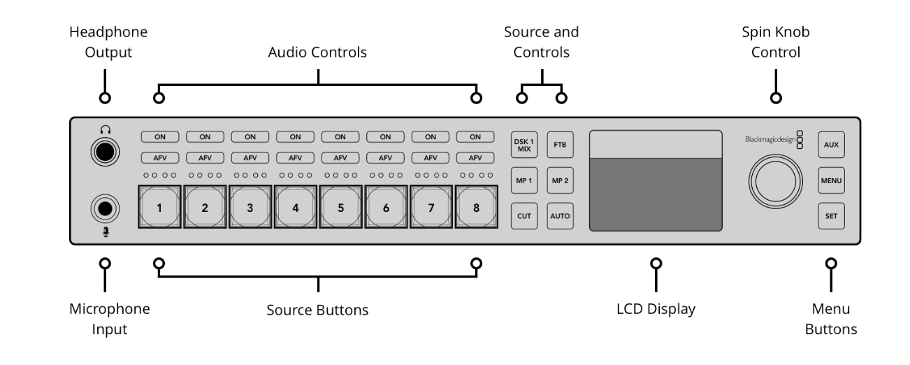
Blackmagic ATEM (Video Switcher)
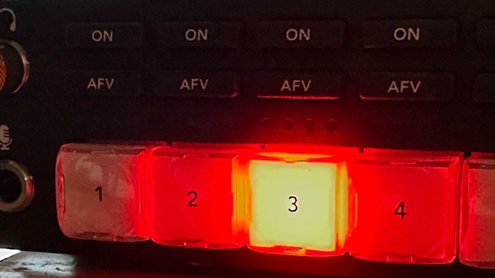
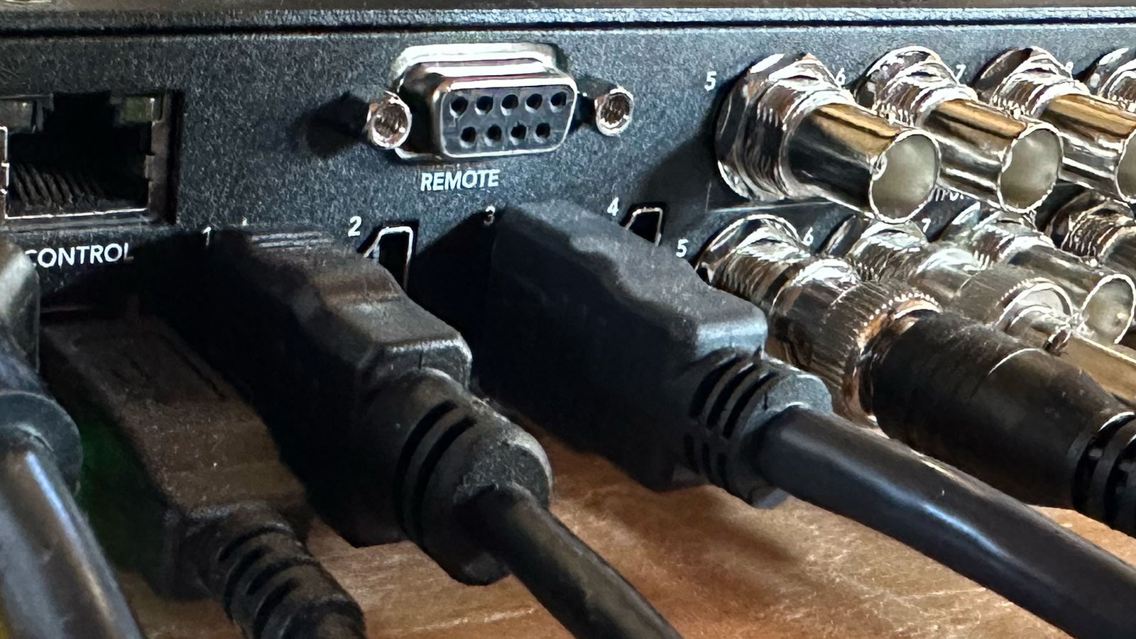
A switcher takes multiple inputs and makes one of them “live” at a time. In the image above, channel 3 is active, or live. The live signal is the one that gets sent out of the device to the feed (the SDI out).
The following diagrams are taken from the Blackmagic Technical Specs
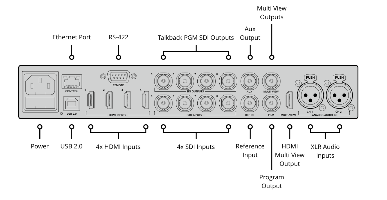
Our particular model accepts 4 HDMI inputs and 4 SDI inputs. Which input gets used largely depends on the need and the device. SDI (Serial Digital Interface) is a professional standard and supports longer cable distances. HDMI (High-Definition Multimedia Interface) is more of a consumer standard and supports shorter cable distances.
The switcher channel buttons on the front of the device and the input channels on the back of the device are one-to-one. Meaning the input for 1 on the rear matches the channel 1 button on the front. It is a pass-through. You can not assign buttons to any input device.
The cameras support SDI. The PowerPoint PC does not and, therefore, requires an HDMI input on the switcher.
Channels 1-4
Channels 1-4 are HDMI inputs. They support shorter cable distances. Channel 1 is linked to the Camera in the booth. It is right next to the switcher and, therefore, does not require a long cable. Channel 3 is connected to the PowerPoint computer, which is a couple of feet away, also in the booth. When you want Camera 1 to be live, you select the Channel 1 button on the front of the switcher. When you want the PowerPoint slide to be live, you select Channel 3.
Channels 5-8

If you notice, the SDI connectors for channels 5-8 have two rows. The bottom row is the input connector. The top row is the output connectors. Channel 5 is connected to the band camera at the rear of the sanctuary at the end of the walkway between the rows that lead to where the piano is on the stage. That is where the band stands. We use channel 5 when we want to cut to the band. There is a larger distance between that camera and the switcher. Therefore, an SDI cable is required.
Channel 6 is connected to the camera in the back of the sanctuary over the entrance door. The channel six camera frames the entire stage and is used when a wide shot of the entire stage is needed. That camera is also a longer distance from the switcher and, therefore, requires an SDI cable. Note: The details of using the various channels are explained in the program script, which is in a separate PDF document. That document will be made available to all production team members.
The Program Output SDI connector goes to the encoder (see below). The HDMI Multi-View Output connector goes to the monitor on the wooden shelf in the booth. This enables us to see the various inputs, queue up a view, and transition the queued view to the live fee.
Zowie Tek SDI encoder
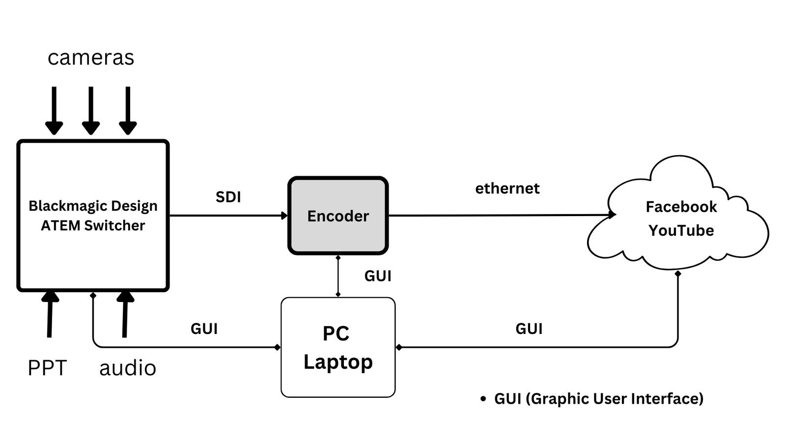
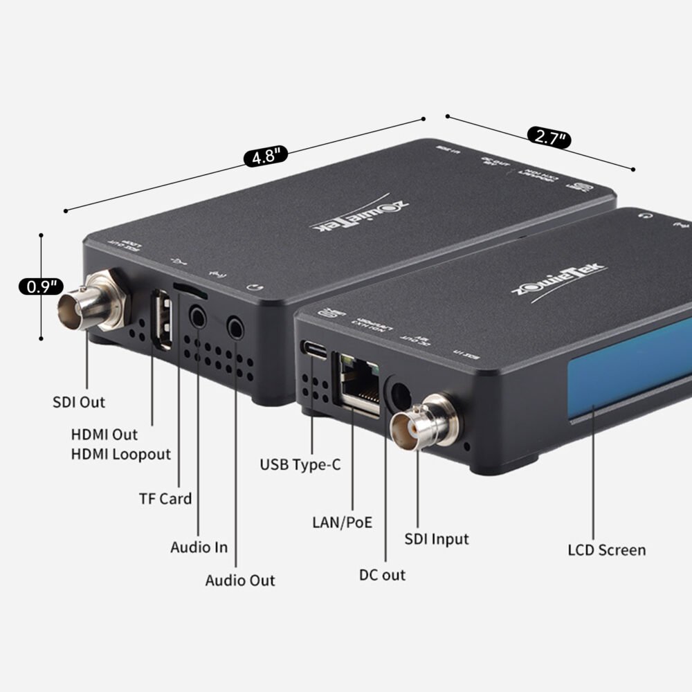
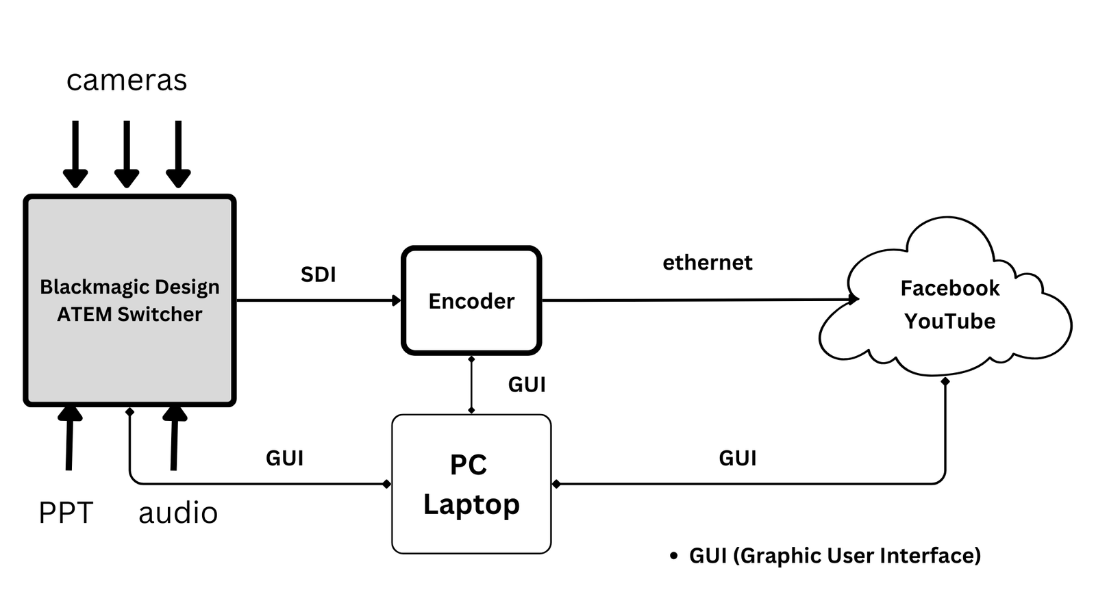
Streaming platforms, e.g. Facebook and YouTube, require a video (video and audio) to be “conditioned” in a certain way. They require certain codecs, bit rates, frame rates, and determine which URI the signal is sent to and the streaming key that is used.Encoders are the devices that perform that function. The Zowie Tek SDI Encoder is a hardware converter that converts, in real-time, a media signal from the SDI input to the internet. The output from the encoder goes directly to the cloud (Facebook and YouTube) via an ethernet port (LAN/PoE).
Resources:
Zowie Tek
- Zowie Tek SDI Encoder Quick Start Guide
- Zowie Tek SDI Encoder > How to stream to YouTube
- Zowie Tek SDI Encoder > How to Stream to FaceFook